24 Results
View results:
Sort by:

Torsional buckling analysis of transverse and longitudinal stiffeners with open cross-sections is described in DIN EN 1993-1-5, Chapter 9. There is a difference between the simplified method and the precise method, which takes into consideration the warping stiffness of the buckling panel. The simplified method applies Equation 9.3 of DIN EN 1993‑1‑5. If warping stiffness is to be taken into account, either Eq. 9.3 or Eq. 9.4 should be followed. Both design methods are implemented in PLATE-BUCKLING.

In SHAPE-THIN, the calculation of stiffened buckling panels can be performed according to Section 4.5 of EN 1993-1-5. For stiffened buckling panels, the effective surfaces due to local buckling of the single panels in the plate and in the stiffeners, as well as the effective surfaces from the entire panel buckling of the stiffened entire panel, have to be considered.

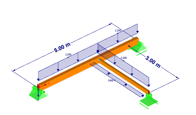
This technical article deals with the stability analysis of a roof purlin, which is connected without stiffeners by means of a bolt connection on the lower flange to have a minimum manufacturing effort.
![System and Loading According to [1]](/en/webimage/009634/2419765/01-en-png-png.png?mw=640&hash=5e657e3feb5c1bb6d21727468dd85d91e1c9f29f)
A structural analysis does not only determine and design internal forces and deformations. It also ensures that the forces and moments in a structure are generated in a reliable way and applied to the foundation. Dlubal Software provides a wide range of products for the structural analysis and design of steel and timber connections. The RF-/JOINTS Steel – Column Base add-on module allows you to design footings of hinged and restrained column bases. The design can be performed for column base plates with or without stiffeners.

If a rib is part of a nonlinear design or is rigidly connected to following walls, a surface should be used for the modeling instead of a member. So that the rib can still be designed as a member, a result member with the correct eccentricity is required, which transforms the surface internal forces into member internal forces.

Plate girder is an economical choice for long spans construction. I-section steel plate girder typically has a deep web to maximize its shear capacity and flange separation, yet thin web to minimize the self-weight. Due to its large height-to-thickness (h/tw) ratio, transverse stiffeners may be required to stiffen the slender web.

Designing rigid end plate connections is difficult for four-row connection geometries and multi-axis bending stresses, because there are no official design methods.
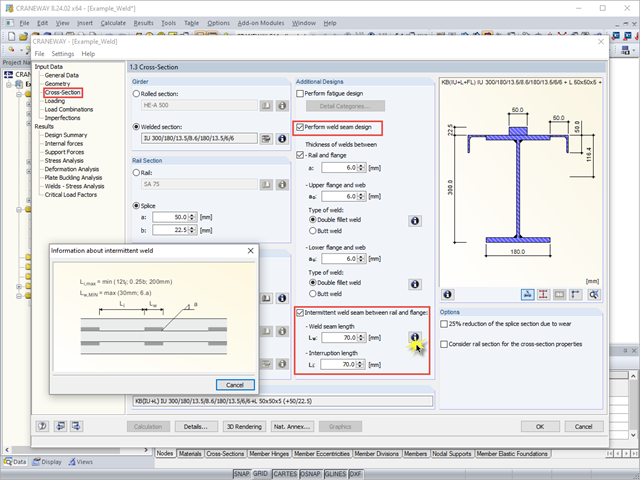
When using interrupted welds between the rail and flange, make sure that the applied weld length does not exceed the length of the rigid load application of the wheel load according to Equation 6.1 in [1].
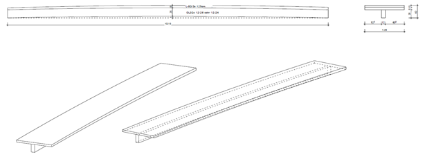
![Structural System and Cross-Section Dimensions According to [1]](/en/webimage/009153/2417271/01-en-png.png?mw=640&hash=c76563b459152b19c98197ea6ba342be89d9a5bc)
There are several options for calculating a semi-rigid composite beam. They differ primarily in the type of modeling. Whereas the Gamma method ensures simple modeling, additional efforts are required when using other methods (for example, shear analogy) for the modeling which are, however, offset by the much more flexible application compared to the Gamma method.
Our client had the exciting task of modeling a cross‑laminated timber plate with a precamber such that, in the case of a span of more than ten meters, the deformation was below the limit value of l/300 = 3.3 cm. The idea was to screw the plate on a glulam beam and then put it together with a glue approved by the building authorities in order to create a rigid bond between the plate and the member.

This article shows you how to define different types of member transverse stiffeners in RFEM 6 and RSTAB 9. It also shows you how to consider them in the design as well as the calculation of members with 7 degrees of freedom.

Line releases are special objects in RFEM 6 that allow structural decoupling of objects connected to a line. They are mostly used to decouple two surfaces that are not rigidly connected or transferring only compressive forces at the common boundary line. By defining a line release, a new line is generated at the same place which transfers only the locked degrees of freedom. This article will show the definition of line releases in a practical example.
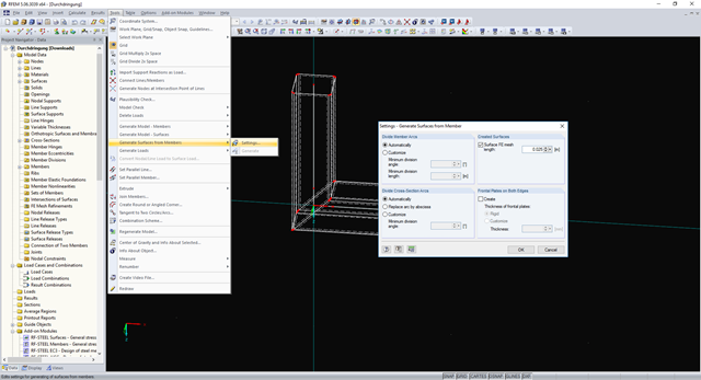
In RFEM, you can generate surfaces from members (for example, to perform an accurate FE simulation on a member). Specific parameters such as automatic FE mesh refinement or rigid surfaces can be defined prior to the generation.
RF-/JOINTS Timber – Timber to Timber allows you to design main-connected beam joints. This article explains the determination of forces in screws of a beam connected to a torsionally rigid main beam.
In particular when the adjacent area of connection points should be analyzed, the geometry or load of the connection does not correspond to the standard specifications, and/or a structure should be analyzed with an FE model (for example, in plant engineering), it is necessary to evaluate the connections in detail on the FE model.
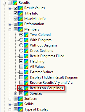
In order to display the internal forces of rigid members, it is necessary to select the corresponding option under ‘Results’ → ‘Members’ → ‘Results on Couplings’ in the Display navigator.

In timber design, beams are often built from several timber elements. The individual elements can be connected with glue, nails, bolts, or dowels. A glued connection is to be assumed as rigid. In the case of dowel‑type fasteners, the joint is compliant (slip joint), and the cross‑section properties of the connected elements cannot be fully applied.

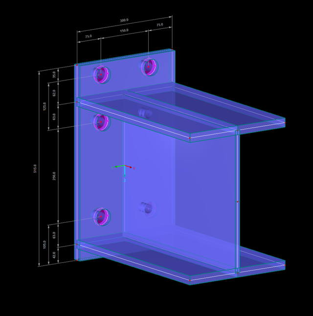
For a timber connection as shown in Figure 01, you can take into account the torsional spring rigidity (spring stiffness for rotation) of the connections. You can determine it by means of the slip modulus of the fastener and the polar moment of inertia of the connection.

This article will show you the Building Model add-on, which has been enhanced with one important advantage: calculating the center of mass and center of rigidity.

In the case of open cross-sections, the torsional load is removed mainly via secondary torsion, since the St. Venant torsional stiffness is low compared to the warping stiffness. Therefore, warping stiffeners in the cross-section are particularly interesting for the lateral-torsional buckling analysis, as they can significantly reduce the rotation. For this, end plates or welded stiffeners and sections are suitable.
RF-LAMINATE allows free definition of materials. Thus, you can combine any compositions of different materials. The combination of concrete and timber is possible as well. However, the rigid composite must be provided when defining such a composition. In RF-LAMINATE, you can consider full shear coupling or no shear coupling at all.

In this example, the design resistance of an end plate according to EN 1993-1-8 [1] is to be determined; the other components are not described here. To check the results, the dimensions of the connection IH 3.1 B 30 24 of Typified Connections [2] were used. S 235 material and bolts with strength 10.9 are used.

The buckling analysis of plates with stiffeners is a special task for engineers. For this, EN 1993-1-5 provides three calculation methods: Effective Cross-Section Method, [1], Sect. 4-7; Reduced Stress Method, [1], Sect. 10; Finite Element Methods of Analysis (FEM), [1], Annex C.

Besides the standardized gamma method, you can display the semi-rigid composite beams also as a framework model.